
Yet another ESP32 Programmer
Yes, you may have seen something like this before. There are a lot of projects of adapters for programming ESP32 and ESP8266 chips. Still, I decided to make my own, covering the features I thought needed for my projects while keeping it functional for others who may be interested in using this board.
What’s the idea behind such a board? When designing products around ESP32, if you won’t need the serial communication via USB, chances are you’ll only use the serial converter when you load the firmware to the ESP32. So, why not have this part of the circuit in another board? Saving space in the main board, and most importantly, reducing costs. All parts of this circuit would only need to be purchased once, instead of every single board you make.
This board acts as a USB to serial converter/bridge while providing power to the target ESP32 (3.3V or 5V available). And also, the famous auto-reset circuit for programming the Espressif chips. Let’s take a look at the board features before going on how it was developed:

-
- USB-C Connector: totally overkill, but this.
- ESD and overcurrent protection: a PTC fuse for overcurrent protection and TVS diodes for ESD.
- USB-to-UART Bridge: the CP2104 is the star of this board, providing communication via USB with the target device.
- 3.3V ~ 600mA regulator: more than plenty for this board and the most basic projects. LEDs for power, and TX/RX lines.
- Auto-reset circuit: needed for automatically programming Espressif devices without needing to manually enter boot mode.
- Boot and Reset buttons: just in case, but you shouldn’t need them.
Maybe the most unusual circuit in this board is the auto-reset, but still, it is fairly simple and popular by now, it’s present in the ESP32-DevKit by Espressif itself, and you can check its schematic for it. A variant of its circuit is also used in the WeMos boards, and that’s the one we chose to use, the main difference with it is that we change the two individual transistors for the 2-in-1 UMH3N, this makes the layout a little more elegant.
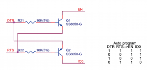
This circuit works as described in the truth table, and what happens is that the esptool.py, used by Arduino IDE and ESP-IDF when uploading firmware to the ESP32, sets the levels of the DTS and RTS pins so the EN pin is LOW, and when it goes to HIGH the IO0 goes to LOW. When the ESP32 boots it checks for the GPIO0 state, if it’s HIGH the ESP32 runs its firmware in normal mode, but if it’s LOW it enters boot mode and is ready for programming. Hence this manipulation done by the esptool.py with this associated circuit can make the ESP32 enter its boot mode automatically.
The rest of the schematic is pretty straightforward, you can check it below. All the PCB files are also available on my GitHub page, everything is open-source, so feel free to make your own PCBs and give me feedback on it.

I do like to make my PCBs as aesthetic as possible without compromising function. This time, I’ve designed a custom truchet tile pattern for the back, with my logo and some buzzard labels. Also: round corners, round curves for the traces and a ground outline. All of these helped to achieve a more beautiful look for the PCB, and are fairly simple to do. In the future, I’ll write a post about this process.
You could use this board as its is (I know I have), but I also designed an enclosure in Fusion360, with a 3d-printed part between two acrylic sheets, for aesthetic purposes. But you can print a whole case and ditch the acrylic, it will be still entirely functional. Those .STL files are also available in the repository.

For now, I believe that covers it all. If you have questions, feel free to hit me up at Discord.