Designing My Own Macropad
After understanding more about the process of building keyboards, I had the idea of designing my own keyboard, instead of buying the parts to build one, as I had most of the required skills and saw it as a good exercise.
Important disclaimer: take everything I say from now on with a grain of salt. I’m not an expert on this hobby, I’m just sharing my learning journey so far, this is a niche that’s really new to me. Most importantly, this isn’t a full step-by-step guide, but rather a journal of the process I went through while doing this. Anyway, I’ll try to include the most references possible, but if you want a true guide on how to build your own mechanical keyboard, besides searching on forums and platforms like Reddit (there’s a ton of information available), there are a few I can recommend:
Ruiqi Mao’s guide is the first that comes to mind, it covers many important points and is straight to the point. Jeremy Patton’s and Sasha Solomon’s guides are also great, and this keyboard designer wiki is fantastic. There are many other great guides online, and you can never research enough, but these helped me a lot and will surely help anyone interested in building their own keyboard.
To make things easier for my first attempt, I decided to design a macropad instead of going for a full-sized keyboard. A macropad has a smaller form factor, and it would be really useful for me as I could make custom shortcuts and macros that would help me with the software I often use for work, such as EAGLE, Fusion 360, and many others.
I searched for all the possible macropads I could find online and learned the layouts and styles that are often used, as an inspiration, but I wanted to design my own layout. There were a couple of boxes I wanted to check: an “irregular” layout, having a knob, and some see-through detail on the case that allow me to have a glimpse of the PCB.
To simplify things even further, I stuck to keycaps smaller than 2u to avoid using stabilizers. Since the project is quite small, it’s ok not having those keys.
There’s a great tool for creating layouts, which I used to better visualize my idea and tweak it until I reach the design I wanted. The keyboard-layout-editor is quite handy, and even though it has a ton of features, such as exporting the layout (which I’ll not get into here), I only used it to have a better visual of the layout. After tinkering a little bit with it, I got to this:
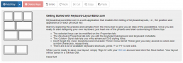
The idea behind the irregular layout is that I intended to use blank keycaps, or perhaps with random symbols, and this layout would help to memorize each button’s function. At that point the knob’s position in this layout and other design details.
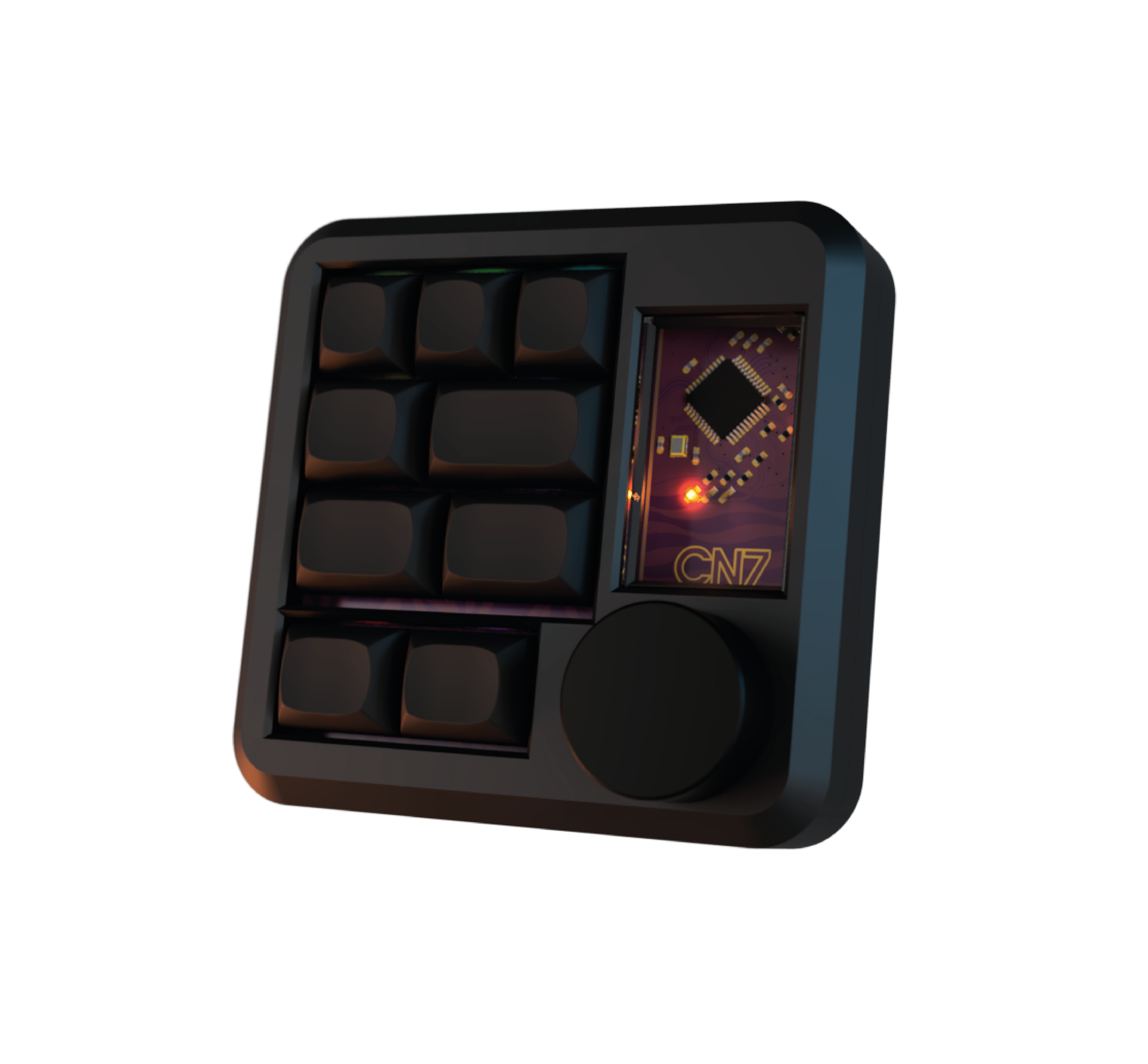
For the overall look, one of the ideas I wanted a see-through window in the case so details of the PCB would remain visible, much inspired by the Argyle Keyboard, the Mercutio 40%, the May Pad, and many others. I’m also inspired by the CU7 and its minimalistic look and huge, but still clean-looking, knob.
Finally, I chose a hot-swappable build, with RGB underglow for the PCB and individual RGB LEDs for each key.
The PCB
The schematic
After researching guides and open-source projects, I noticed that the vast majority of them use KiCad, but my current workflow is better with Autodesk EAGLE/Fusion360. I couldn’t find many resources on this matter for EAGLE, so I knew I would have to create a few of the components I would use on the board, specifically the keys.
For the switches, there are a few EAGLE libraries available, but none checked all the boxes I wanted: different sizes of keycaps, as my layout uses 1u, 1.25u, 1.5u and 1.75u, and the footprint for the Kailh sockets used so it the switches could be hot-swappable. I created the footprints, using a few available libraries as a base, along with the datasheets for the socket and the switch:
- Kailh Socket Datasheet
- Cherry MX Datasheet
- SparkFun Cherry Breakout Board Library
- Clueboard Library
- VinnyCordeiro’s Kailh Library
I also found this chart of the sizes for each keycap, which came in handy for creating a variant component for each of the sizes I was going to use. This section of matt3o’s guide was also quite useful. Grabcad has a ton of 3d models for the switches, keycaps and even the Kailh sockets, and I used those on the EAGLE’s 3D Package Editor to create the packages for the components.
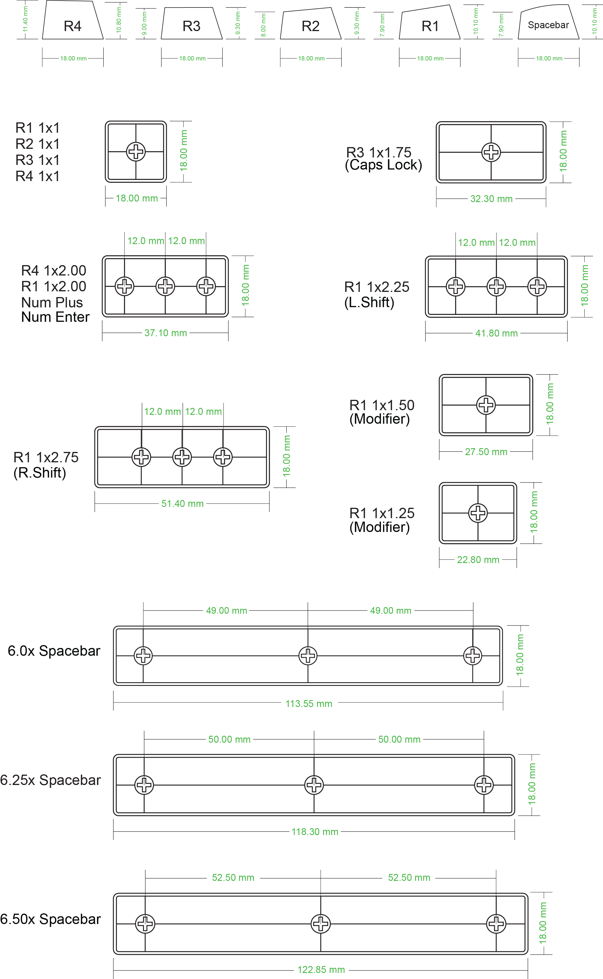
Creating footprints with size guidelines made later placement much easier.
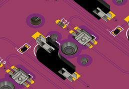
It’s also worth mentioning the use of the SK6812 MINI-E RGB leds, which has become a trend among keyboard builders, for being so low-profile. It’s imilar to the WS2812 (Neopixel), but uses an unusual mounting style where the pads are soldered on the bottom of the PCB, and there’s a hole for the light to shine through. They became so popular mostly for leaving free space for the switch to sit on top of the PCB. This video depicts it greatly. Well, I had to design the footprint for this component too, based on the measures found on its datasheet.
These were most of the components I designed myself, the rest are common packages easily available in EAGLE libraries.
For the board’s microcontroller, there are a few popular options, the Adafruit MacroPad RP2040, one of my inspirations for starting this project, uses the Raspberry Pi Pico RP2040 microcontroller, a lot of makers use STM32 chips, but the Atmega32u4, as seen on the Arduino Leonardo, the Elite-C V4, the Teensy 2.0 and the Pro Micro, remais the most popular. These boards are often used, especially on hand-wired builds. If that is something you might be into, I can recommend this awesome guide.
One thing these microcontrollers have in common is their support to native USB, which means they can be seen by the computer as a common USB interface device.
I chose Atmega32u4 mostly for its popularity. Also, going for a hand-wired build is a common first step for most people, but since I had the expertise in designing circuits and PCBs, I chose to skip this step and go straight for a PCB one. Even though some keyboards use a PCB with one of these boards soldered directly on it, since I was going through all the trouble of designing the whole thing, I decided to use the Atmega32u4 not in a development board, but embedded on my own board.
The circuit is fairly simple, the schematic will be available by the end of this post. The main points of attention here are the oscillator circuit with the crystal and capacitors, the reset button, and decoupling capacitors on every power pin as far as the MCU goes. For the rest of the circuit:
- The connector of choice was USB-C, and you should be aware of the resistors on the data pins: on D+ and D- you should use 22 ohms resistors, and on CC1 and CC2 5.1k ohms resistors. At first I used 5.1k resistors on all pins and my computer didn’t recognize the board, so mind that.
- I chose to expose the ICSP pins, in case I would need to burn a bootloader to the MCU. In theory that shouldn’t be necessary if you buy the right part (there are two versions of the chip, and one of them comes with a bootloader already). But, as it turned out, the ICs shipped to me came with a faulty bootloader so this was one of the best decisions I made, saved me a lot of time.
- As far as lighting, I used two types of RGB LEDs, the SK6812 MINI-E under each keycap, and a couple of WS2812b LEDs under the board, for that sweet RGB underglow. And I also placed two regular LEDs on the RX and TX lines, for debugging, and another three so I could see which layer/mode is active.
- Since I had 9 keys, I chose to use a 3×3 keyboard matrix, quite standard, with diodes.
The layout
The first step on designing the layout is component placement. Having already planned the key layout and designing their footprints with proper documentation of each keycap size and distance between them (I chose to leave 1mm between each key), this part was a lot easier.
For the encoder, I had to decide here the size of the knob I would use, since this would impact on the ideal position for it. The rest of the circuit I tried to keep tight in one corner of the board, where I would have a see-through acrylic window for it. For that reason, most of that components are rotated in 45 degrees, only for aesthetics.
In this step I also designed the board shape, using curved corners and some mounting holes.

I also designed a plate to help lining up the switches. There are a couple ways this can be done, it can be 3d printed, laser-cut, and from all sort of materials, like brass, aluminum, plastic, and so on, but I made a PCB to do this job, no traces or connections, just a simple FR4 plate.
Designing the case
After ordering the PCBs and parts from China, I knew I’d have to wait for a couple weeks, even a month, for them to arrive, so I used this time to focus on designing a case for the macropad. Since I had access to a 3d printer I decided to design a case to be FDM printed, with PLA. Staying within the Autodesk environment, I used Fusion 360 to design it, which kept my workflow smooth.
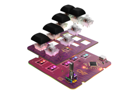
Pushing the board design to Fusion is straight-forward, and when designing the board I took the time to find 3d files for each of its components, such as the encoder, switches, sockets, ICs, resistors and connectors. The exported board in Fusion was as true-to-life as possible. This allowed me to start this design even before receiving the boards and assembling them, as it wasn’t really needed to double-check dimensions.
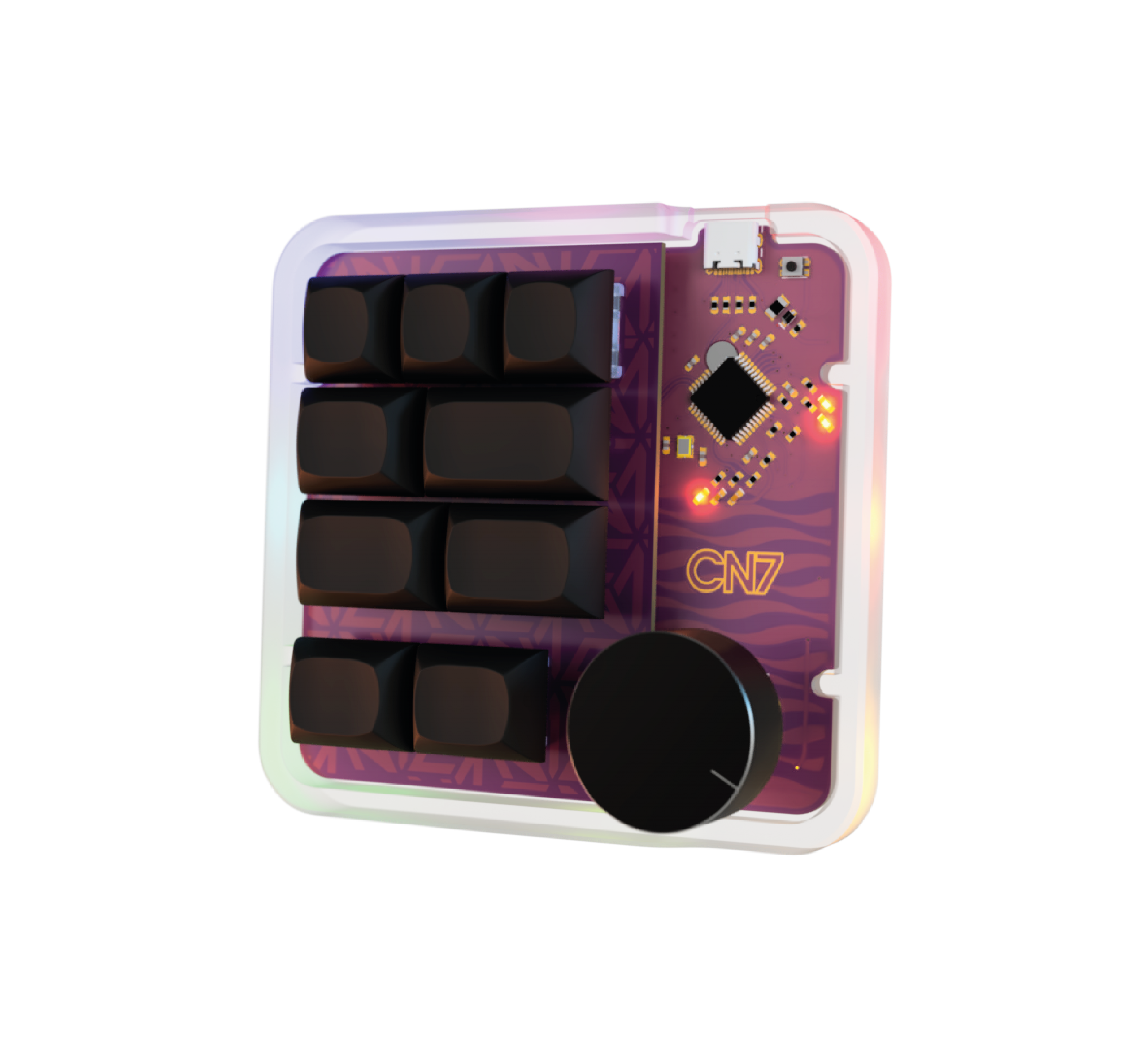
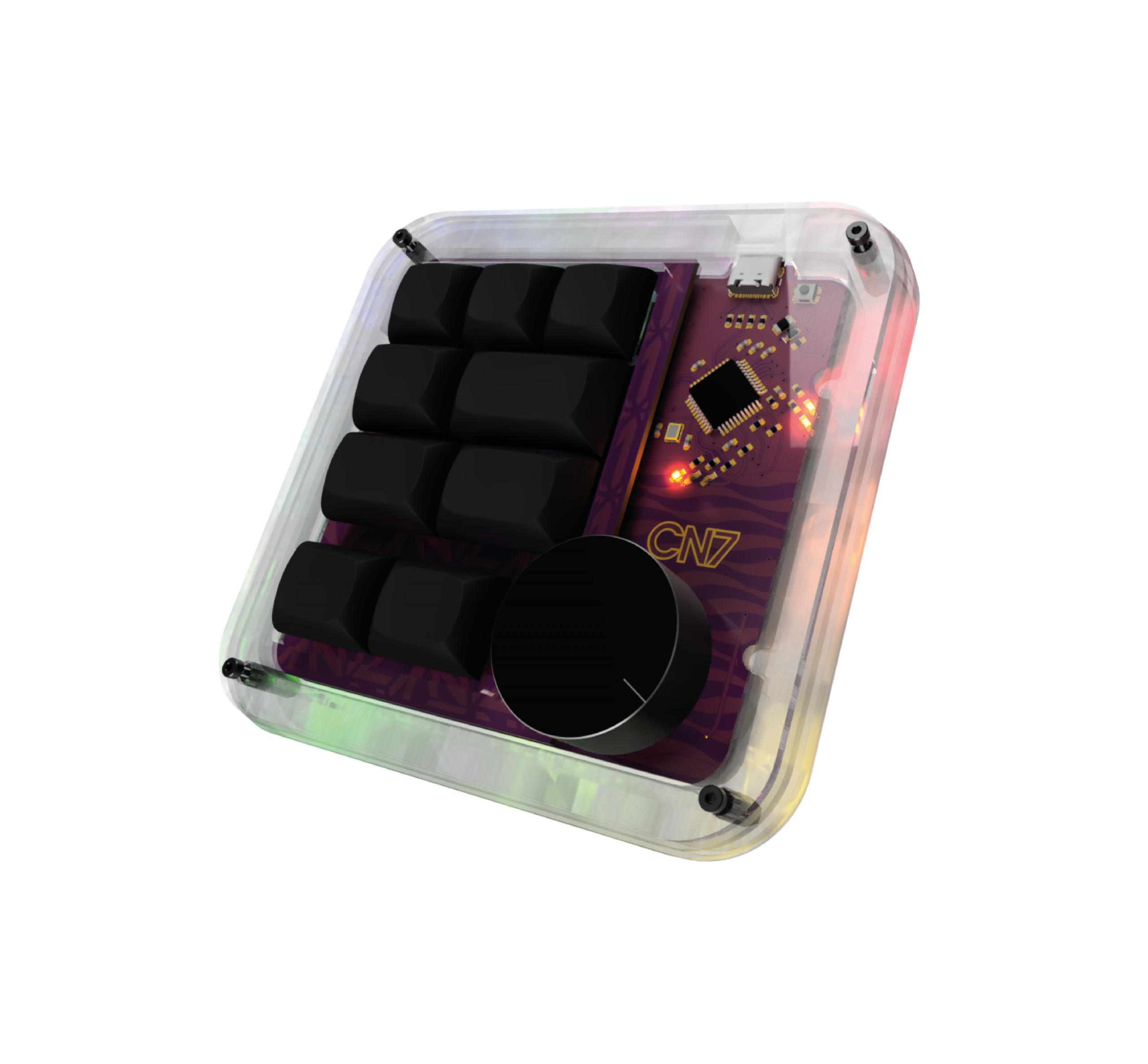
And so I’ve designed three versions, one printed in black PLA, with a acrylic window to let the PCB in display. Another one with just a clean base, printed in transparent/white PLA. And finally my favorite, a stacked acrylic case, which turned out great considering it was my first try designing one. I’ve designed every acrylic layer on Fusion and exported the sketch to Illustrator.